
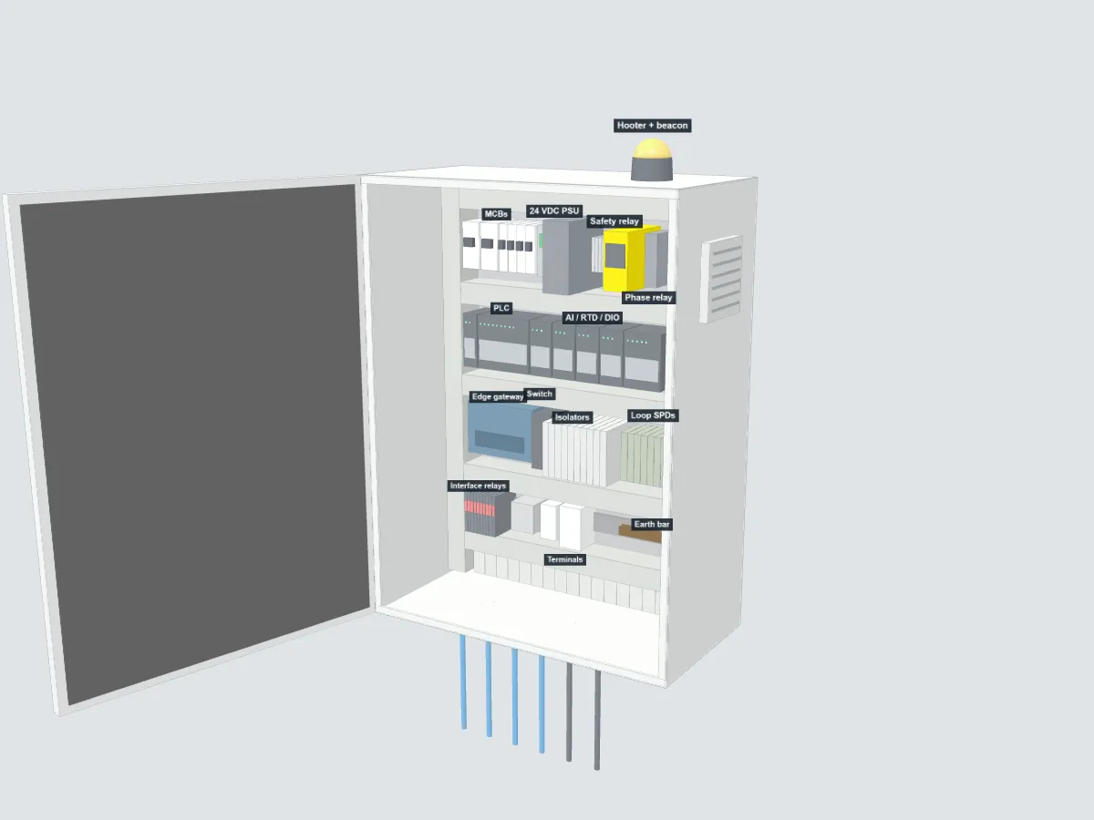
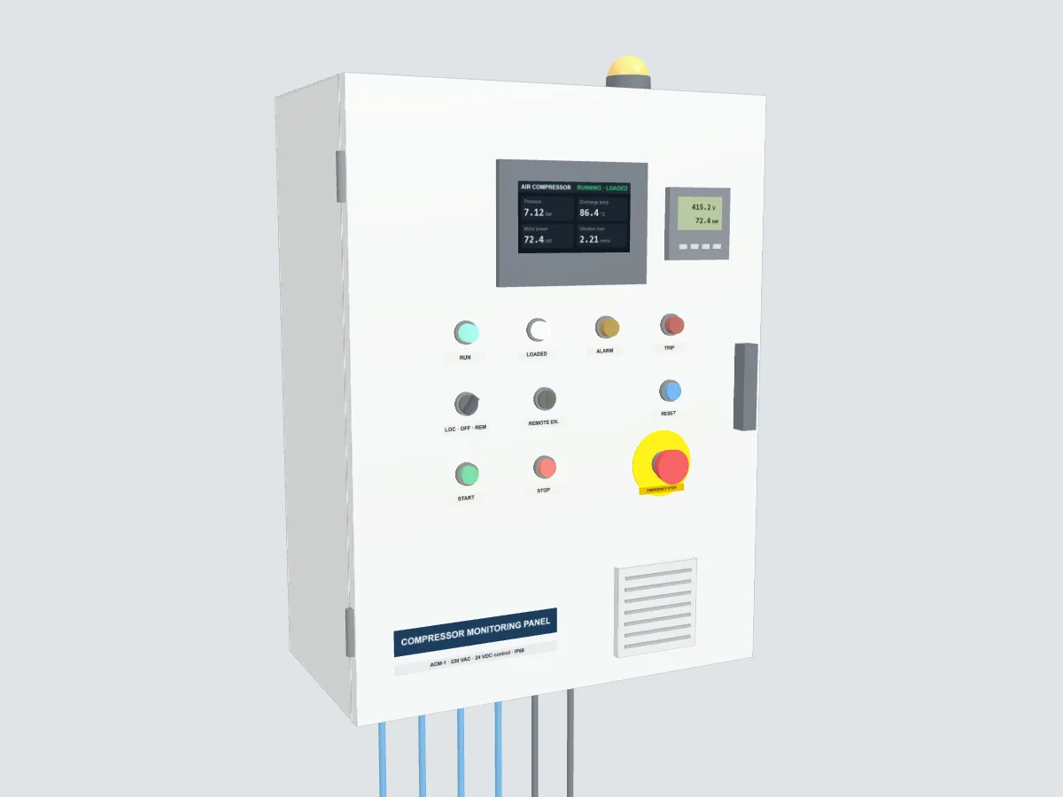
Drag to orbit, scroll or pinch to zoom, hover a part to see what it does. The HMI, energy meter and lamps run on simulated demo data: switch on Alarm or Trip, or switch off Running, to see the panel respond.
Condition monitoring
ACM-1 Industrial Air Compressor Monitoring Panel
Watches pressure, temperature, vibration, power, flow and dew point on a rotary screw compressor, and alarms or trips before damage is done.
- Suits
- Oil-injected rotary screw compressors
- Monitors
- Pressure, temperature, vibration, power, flow, dew point
- Alarms
- Door lamps, hooter and beacon, HMI, web dashboard
- Enclosure
- Wall-mount 800 × 600 × 300 mm, IP66
- Control
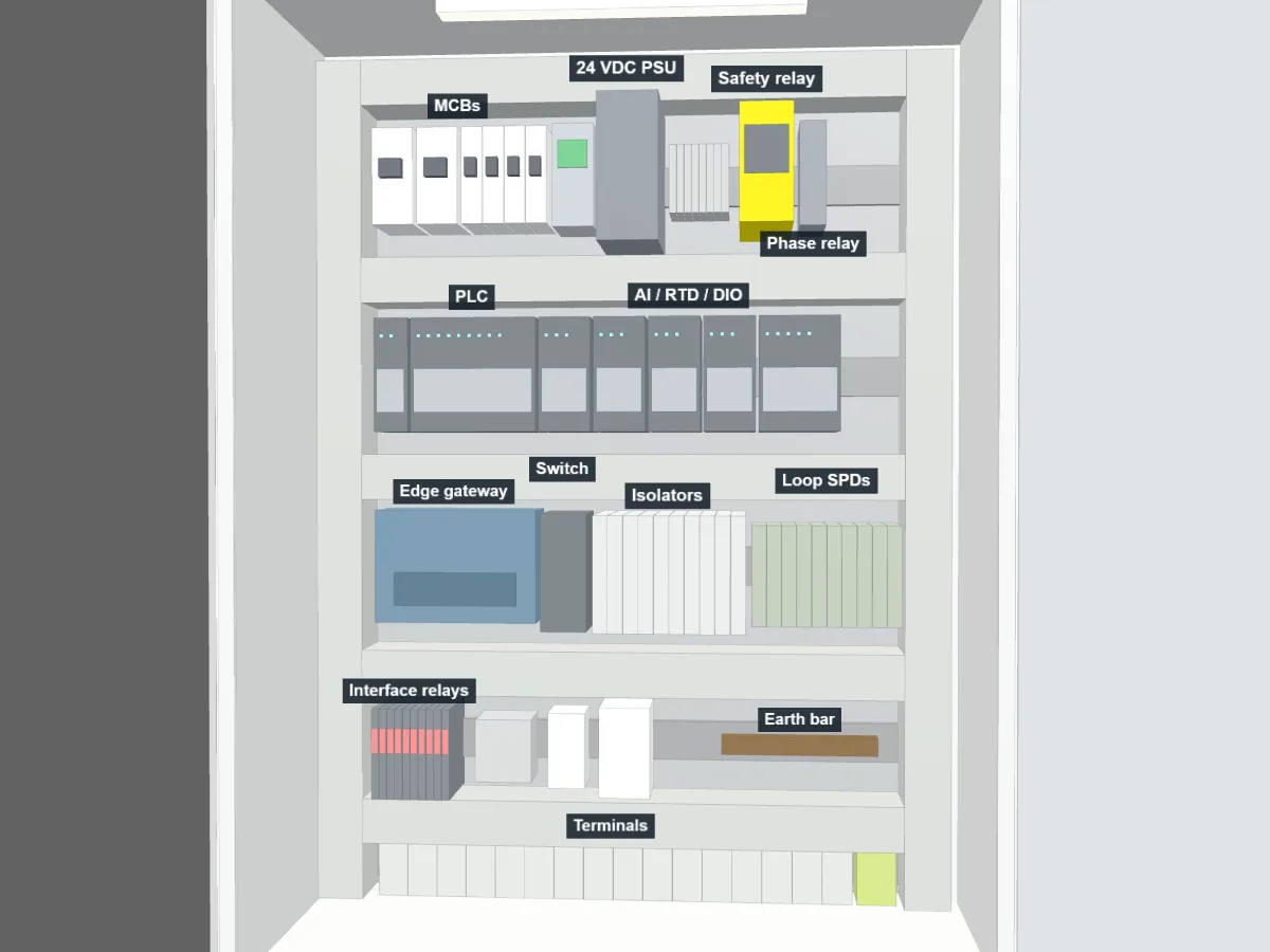
- PLC with hard-wired E-stop safety relay
- Supply
- 230 VAC, 24 VDC control
Built for your compressor. Lead time is confirmed with the quotation.
Overview
See a compressor's condition before it trips.
The ACM-1 adds condition monitoring and protection to an oil-injected rotary screw compressor. It reads the pressure, temperature, vibration and electrical signals that show wear early, raises alarms on the panel and the plant network, and stops the machine when a limit is crossed. Each panel is built for your compressor, and setpoints are set at commissioning from the maker's manual.
Protection runs in the PLC and hard-wired relays. The web dashboard only monitors and acknowledges alarms, so a network fault never affects the machine.
Product preview
Door and back plate
Monitoring
Parameters monitored
Analog transmitters are 2-wire 4–20 mA through isolators and surge protection; temperatures are 3-wire PT100 Class A. The list is adapted to your compressor's existing instruments.
| Discharge pressure | 4–20 mA transmitter | 0–16 bar(g) |
|---|---|---|
| Sump / separator vessel pressure | 4–20 mA transmitter | 0–16 bar(g) |
| Separator element ΔP | Calculated | 0–2 bar |
| Oil filter ΔP | 4–20 mA transmitter | 0–2.5 bar |
| Air intake filter ΔP | 4–20 mA transmitter | 0–100 mbar |
| Airend discharge | PT100 | 0–150 °C |
|---|---|---|
| Oil injection | PT100 | 0–150 °C |
| Aftercooler outlet air | PT100 | 0–100 °C |
| Motor windings U, V, W | PT100 (built into the motor) | 0–200 °C |
| Motor bearings DE and NDE | PT100 | 0–150 °C |
| Compressor room and panel | PT100 | 0–80 °C |
| Motor drive-end bearing | Velocity RMS, 10–1000 Hz | 0–25 mm/s |
|---|---|---|
| Motor non-drive-end bearing | Velocity RMS, 10–1000 Hz | 0–25 mm/s |
| Airend | Velocity RMS, 10–1000 Hz | 0–25 mm/s |
| Voltage, current per phase and imbalance | Energy meter, Modbus RTU | Class 0.5S |
|---|---|---|
| Power, power factor and energy | Energy meter | kW, kVAr, PF, kWh |
| Harmonic distortion | Energy meter | THD |
| Phase loss and reversal | Phase monitoring relay | Trip |
| Motor and cooler fan overloads | Starter contacts | Status |
| Free air delivery | Thermal mass flow meter | 0–20 m³/min |
|---|---|---|
| Specific power | Calculated from kW and flow | kW per m³/min |
| Pressure dew point after the dryer | 4–20 mA transmitter | −20 to +50 °C |
| Dryer and condensate drain | Status contacts | Running / fault |
| Running, loaded and unloaded | Contactor and valve feedback | Status |
|---|---|---|
| Oil level | Level switch | Low |
| Running hours and starts per hour | Calculated | Service planning |
Protection
Alarms and trips
Setpoints and delays are set at commissioning from your compressor's manual. Trips latch and reset only at the panel; the web dashboard can acknowledge alarms but never reset a trip.
| Condition | Response | Notes |
|---|---|---|
| Emergency stop pressed | Trip | Hard-wired, stops at once |
| Phase loss or reversal | Trip | |
| Main motor or cooler fan overload | Trip | |
| Star/delta contactor feedback mismatch | Trip | |
| Airend discharge temperature high | Trip | Alarm first, trip at high-high |
| Motor winding temperature high | Trip | Alarm first, trip at high-high |
| Vibration in zone C / zone D (ISO 10816-3) | Trip | Alert at zone C, trip at zone D |
| Discharge pressure high (unload failure) | Trip | Unloads first, trips at high-high |
| Oil level low | Trip | |
| Motor bearing temperature high | Controlled stop | Alarm first, controlled stop at high-high |
| Separator element ΔP high | Controlled stop | Plan a replacement; controlled stop at high-high |
| Transmitter fault (wire break, signal out of range) | Controlled stop | Controlled stop if it is a protection input |
| Oil filter or air filter ΔP high | Alarm | |
| Pressure dew point high (dryer) | Alarm | |
| Condensate drain fault | Alarm | |
| Panel temperature high | Alarm | |
| Service interval due | Alarm | |
| Sump still pressurised at a start request | Start blocked | |
| Too many starts in an hour | Start blocked | |
| Oil too cold to load | Start blocked | Runs unloaded until warm |
Want one for your compressor?
Add it to your basket and request a quotation. Tell us the compressor make, rating and existing instruments, and we will size the panel to match.
Specifications are subject to change without notice. Printed from https://varinautomation.com/products/acm-1.