
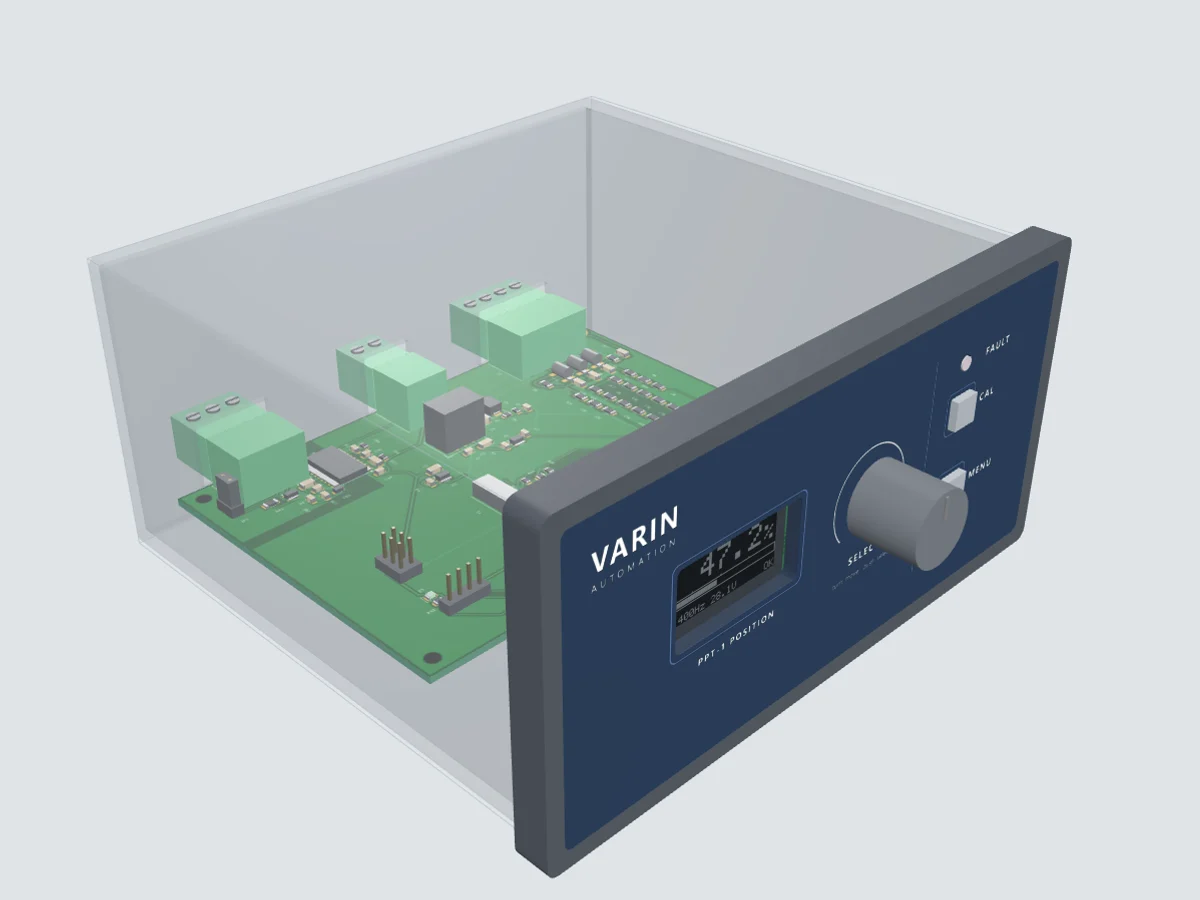
Drag to orbit, scroll or pinch to zoom, hover a part for its reference. Built from the PPT-1 Rev A board design; housing shown see-through, the display shows the real firmware screen.
Position measurement
PPT-1 Position Transmitter
Reads a potentiometer on 28 V DC or 400 Hz AC and shows its position in %, mm or degrees, on the panel and over Modbus RTU.
- Input
- 3-wire potentiometer
- Excitation
- 10–51 V peak, DC or AC
- Display units
- %, mm or degrees
- Interface
- Isolated RS-485 Modbus RTU
- Supply
- 12–30 V DC, about 1 W
- Housing
- DIN 144 × 72 mm panel mount
Delivery within 4 weeks of order · anywhere in India
Overview
Read a potentiometer's position without loading its circuit.
The PPT-1 reads the position of a potentiometer that is already powered by 28 V DC or 28 V AC (400 Hz typical) and shows it on a panel display and over Modbus RTU. It samples the wiper and the excitation at the same instant, so the reading is a true ratio and does not move when the excitation voltage changes.
Each input is over 5 MΩ, so the PPT-1 can sit alongside an existing indicator or controller without loading the sensor. It accepts ±50 V between the pot circuit and its own ground, and 90 V gas discharge tubes to PE protect the input from surges on field wiring.
Choose %, mm or degrees, set zero and full scale with the CAL key, and read position, excitation and fault status from a Delta (or any Modbus RTU master) HMI over isolated RS-485. It fits a standard 144 × 72 mm DIN panel cut-out.
- DC or AC excitation
- 10–51 V
- Input impedance
- > 5 MΩ
- Position updates
- 10 / s
- RS-485 Modbus RTU
- Isolated
Why engineers choose the PPT-1
- Ratiometric readingWiper and excitation sampled together by a 24-bit ADC, so supply swings don't shift the position.
- DC or AC excitation10–51 V peak, DC or AC from about 25 Hz to 1 kHz, including 28 V DC and 28 V AC 400 Hz.
- Doesn't load the sensorOver 5 MΩ per input, ±50 V common-mode range and 90 V gas discharge tubes to PE.
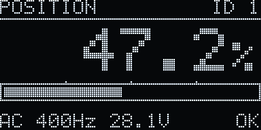
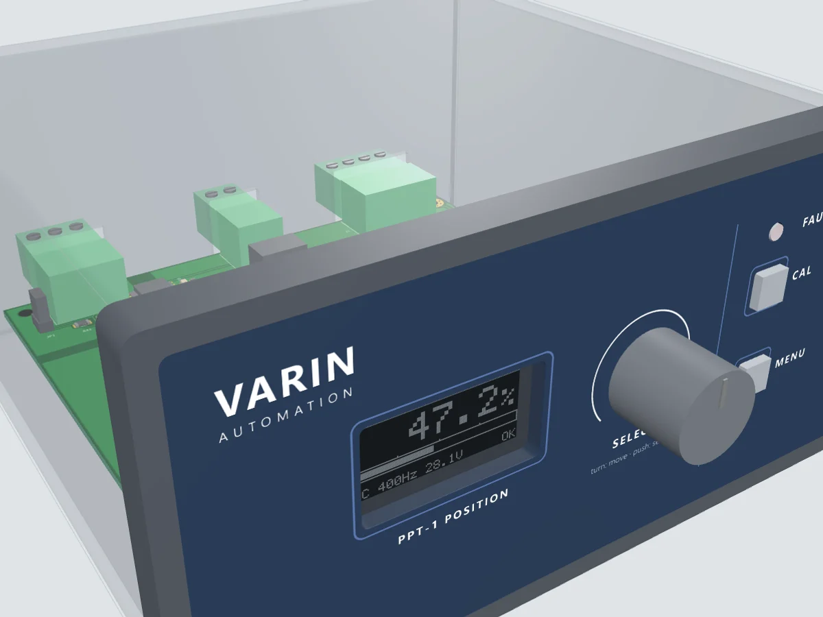
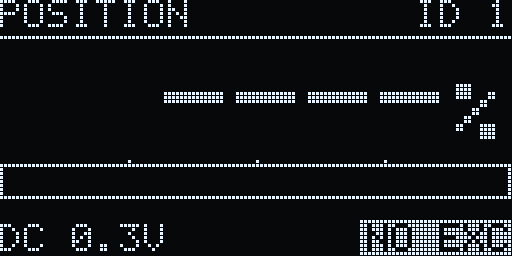
- Clear front panel1.3" OLED with position, bar graph, excitation type, frequency, voltage and status.
- Two-step calibrationMove to zero, press; move to full scale, press. Stored in EEPROM, from the panel or over Modbus.
- Fault detectionFlags lost excitation, an open or out-of-range wiper and over-range, with a red FAULT lamp.
- Isolated Modbus RTURS-485 at 9600, 19200 or 38400 baud with function codes 03, 04, 06 and 16.
- Quick wiringPluggable 5.08 mm terminals on the rear for power, sensor and RS-485.
- Potentiometric position sensors
- Valve & actuator position feedback
- 28 V DC and 400 Hz AC systems
- Linear & rotary pot readout
- HMI & SCADA position monitoring
- Test benches
Product preview
Front panel, terminals, electronics and screens
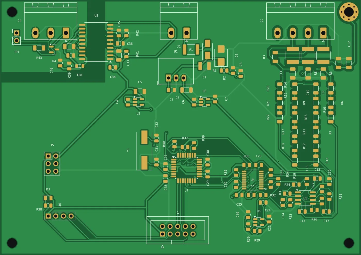
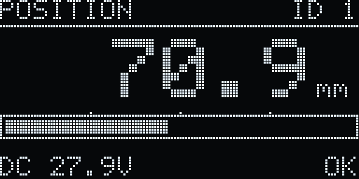
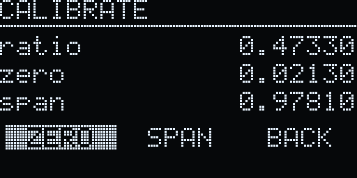
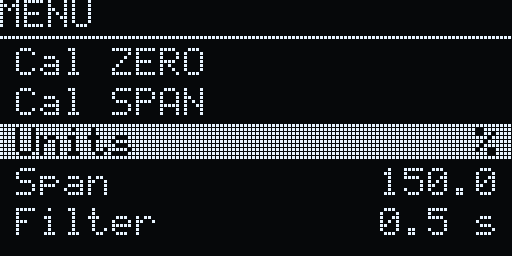
Specifications
Technical data
| Sensor | 3-wire potentiometer: excitation +, excitation −, wiper, plus shield / PE |
|---|---|
| Excitation (from the sensor circuit) | 10–51 V peak, DC or AC, e.g. 28 V DC or 28 V AC 400 Hz |
| AC frequency | About 25 Hz to 1 kHz |
| Input impedance | EXC+ 6.14 MΩ, EXC− 6.14 MΩ, wiper 5.78 MΩ (DC and 400 Hz) |
| Common-mode range | ±50 V between the pot circuit and the transmitter ground |
| Surge protection | 90 V gas discharge tubes to chassis / PE |
| Method | Ratiometric: wiper and excitation sampled together by a 2-channel 24-bit ADC |
| Position | 0–100 % (0.01 % over Modbus), or mm / degrees with a user-set span |
|---|---|
| Update rate | 10 results per second |
| Filter | 0.1, 0.5, 1 or 2 s |
| Calibration | 2-point zero and span, from the panel or over Modbus, stored in EEPROM |
| Also measured | Excitation voltage (RMS for AC), frequency and supply voltage |
| Fault detection | No excitation (< 10 V), wiper fault (open or ratio outside 0.02–0.98), over-range |
| Interface | RS-485, 2-wire, galvanically isolated |
|---|---|
| Protocol | Modbus RTU slave; function codes 03, 04, 06, 16 |
| Address | 1–247 (default 1) |
| Baud rate | 9600, 19200, 38400 (default 9600) |
| Framing | 8N1 |
| Bus termination | 120 Ω, jumper selectable |
| Display | 1.3" 128 × 64 OLED |
|---|---|
| Controls | Rotary encoder with push, CAL key, MENU key |
| Indicator | Red FAULT lamp |
| Main screen | Position and bar graph, excitation type, frequency and voltage, status |
| Supply | 12–30 V DC, about 1 W |
|---|---|
| Supply protection | Resettable fuse, reverse-polarity diode and surge clamp |
| Housing | DIN 144 × 72 mm (IEC 61554) panel instrument case |
| Panel cut-out | 138 (+1.0) × 68 (+0.7) mm |
| Mounting | Panel clamps from behind |
| Field terminals | Pluggable 5.08 mm blocks on the rear: power, sensor, RS-485 |
| Firmware | v1.0, field-updatable over ISP |
Wiring
Rear terminals
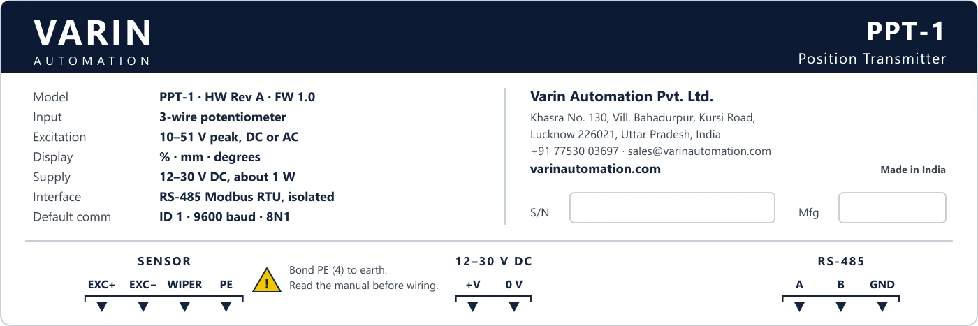
Pluggable 5.08 mm blocks on the rear. Connect the PPT-1 across the existing pot: its high-impedance inputs read the excitation already on the circuit and do not supply it. Bond terminal 4 to PE so the surge protection has a path to earth.
RS-485
Modbus RTU (isolated)
- ARS-485 A
- BRS-485 B
- GNDIsolated signal ground
SENSOR
Potentiometer input
- 1Excitation +
- 2Excitation −
- 3Wiper
- 4Shield / PE
POWER
12–30 V DC
- +VSupply +
- 0 VSupply 0 V
Ordering
Codes and what's included
| PPT-1 | Potentiometer Position Transmitter, DC or AC excitation, front panel + isolated RS-485 Modbus RTU |
|---|
| PPT-1 in DIN 144 × 72 mm housing with panel clamps |
| Mating pluggable terminal plugs for power, sensor and RS-485 |
| Wiring and Modbus register guide |
Modbus RTU
Register map
1-based addressing: 30001 and 40001 are protocol address 0. Floats use two registers, high word first.
| Address | Register | Access | Meaning |
|---|---|---|---|
| 30001 | POSITION | R | Position in 0.01 % |
| 30002–30003 | POSITION_UNITS | R | Position in the chosen units (float) |
| 30004 | RATIO | R | Wiper ratio × 10000 |
| 30005 | EXC_VOLTS | R | Excitation in V × 100 (RMS for AC) |
| 30006 | EXC_FREQ | R | Excitation frequency in Hz × 10 (0 = DC) |
| 30007 | STATUS | R | Bits: no excitation, wiper fault, over-range, not calibrated |
| 30008 | SUPPLY | R | Supply in V × 100 |
| 40001 | ADDRESS | R/W | Slave address 1–247 |
| 40002 | BAUD | R/W | 0 = 9600, 1 = 19200, 2 = 38400 |
| 40003 | UNITS | R/W | 0 = %, 1 = mm, 2 = degrees |
| 40004–40005 | SPAN | R/W | Full-scale value in mm or degrees (float) |
| 40006 | FILTER | R/W | 0 = 0.1 s, 1 = 0.5 s, 2 = 1 s, 3 = 2 s |
| 40007 | COMMAND | W | 1 = capture zero, 2 = capture span, 3 = factory reset |
| 40008–40011 | CAL_ZERO / CAL_SPAN | R/W | Calibrated ratios at zero and full scale (floats) |
Need it in your panel or test bench?
Add it to your basket and request a quotation, or talk to us about HMI screens and integration.
Specifications are subject to change without notice. Printed from https://varinautomation.com/products/ppt-1.