
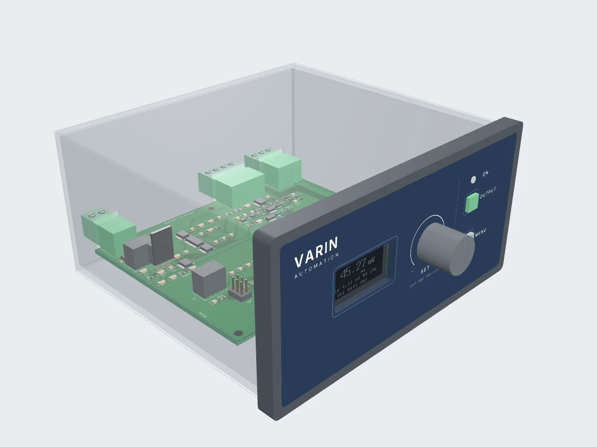
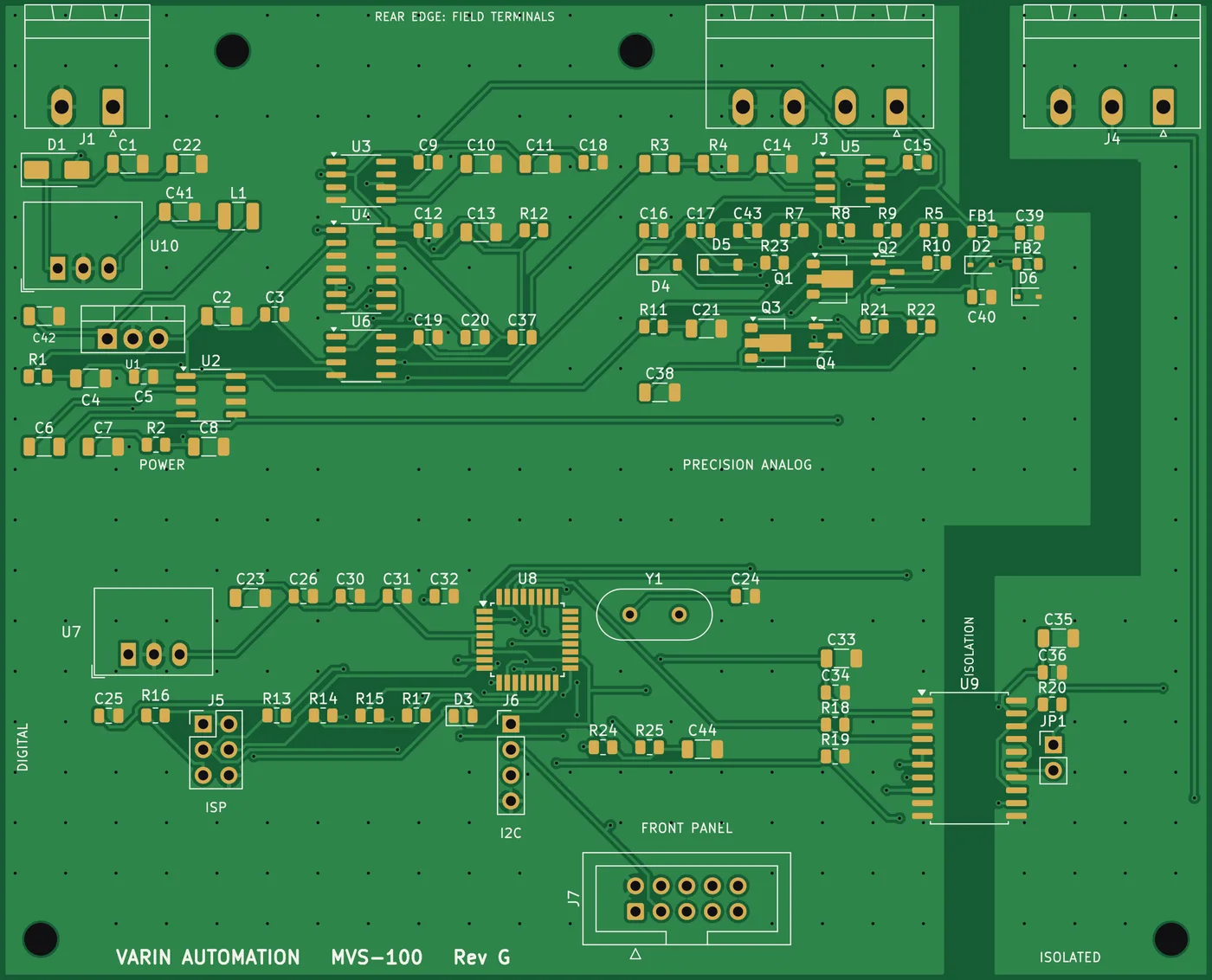
Drag to orbit, scroll or pinch to zoom, hover a part for its reference. Housing shown see-through; the display shows the real firmware screen.
Calibration & test
MVS-100 Precision mV Source
±100 mV in 0.01 mV steps, set from the front panel or an HMI over Modbus RTU.
- Output
- −100.00 … +100.00 mV DC
- Resolution
- 0.01 mV
- Load current
- ±20 mA, source and sink
- Interface
- Isolated RS-485 Modbus RTU
- Supply
- 12–24 V DC, 3 W max
- Housing
- DIN 144 × 72 mm panel mount
Overview
A dependable millivolt reference for your panel or bench.
The MVS-100 generates a stable DC millivolt signal from −100.00 to +100.00 mV for checking and calibrating thermocouple inputs, load-cell and strain-gauge amplifiers, transmitters and DAQ channels. It fits a standard 144 × 72 mm DIN panel cut-out, so a test bench or panel door gets a permanent, repeatable reference.
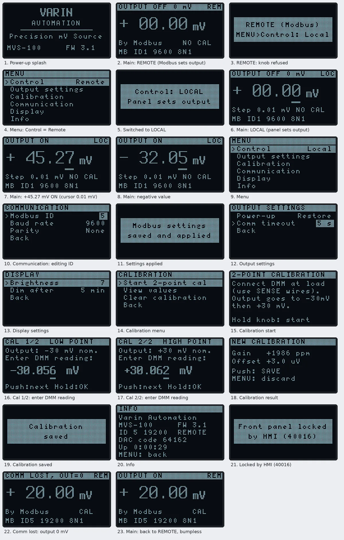
Set the output from the front panel with the knob, or hand control to a Delta (or any Modbus RTU master) HMI over isolated RS-485. Only one place controls the output at a time, and the display always shows which: REM, LOC or LCK.
A 4-wire Kelvin output with remote sense corrects cable drop at the load, and the output stage sources and sinks up to 20 mA. If the HMI link is lost, a configurable timeout drops the output to 0 mV.
- Output range
- ±100 mV
- Setting steps
- 0.01 mV
- Source and sink
- ±20 mA
- RS-485 Modbus RTU
- Isolated
Why engineers choose the MVS-100
- Fine, stable output−100.00 to +100.00 mV DC in 0.01 mV steps, from a 3.18 µV hardware resolution.
- Sources and sinks 20 mA4-wire FORCE / SENSE output corrects cable drop right at the load.
- Isolated Modbus RTURS-485 at 9600–115200 baud with function codes 03, 04, 06 and 16.
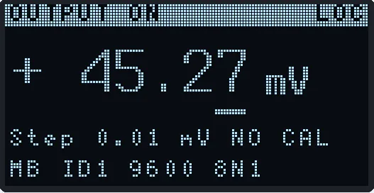
- Clear front panel1.3" OLED, rotary knob, OUTPUT and MENU keys, and an output-ON lamp.
- Remote or local controlOne place controls the output at a time; the HMI can lock the front panel.
- Guided calibration2-point calibration from the panel or over Modbus, stored in EEPROM.
- Fails safeComm-loss timeout drops the output to 0 mV, and OFF holds a calibrated 0.00 mV.
- Quick wiringPluggable 5.08 mm terminals on the rear for power, output and RS-485.
- Thermocouple input checks
- Strain-gauge & load-cell amplifiers
- Transmitter calibration
- DAQ & PLC analog input testing
- Automated test equipment (ATE)
- Panel-mounted reference source
Product preview
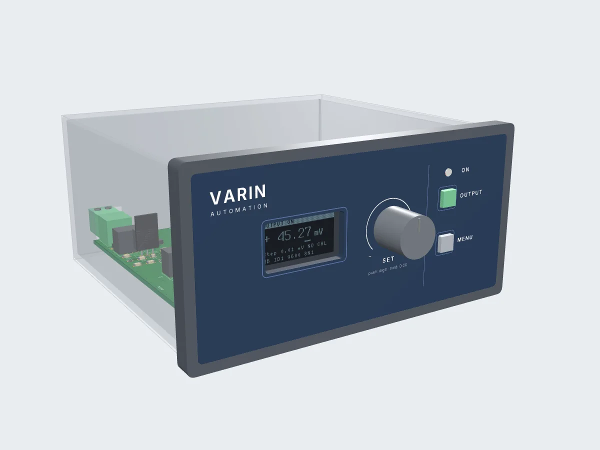
Front panel, terminals and electronics
Specifications
Technical data
| Range | −100.00 to +100.00 mV DC |
|---|---|
| Setting resolution | 0.01 mV (3.18 µV hardware resolution) |
| Load current | ±20 mA, sources and sinks (current limit ≈ 28 mA) |
| Connection | 4-wire: FORCE+, SENSE+, SENSE−, FORCE− / GND |
| Verified accuracy after calibration | ±0.01 mV at +100, 0 and −100 mV |
| Settling | ≈ 1.6 ms to 1 µV after a 10 mV step |
| Output OFF / comm loss | Actively held at 0.00 mV (calibrated) |
| Interface | RS-485, 2-wire, galvanically isolated |
|---|---|
| Protocol | Modbus RTU slave; function codes 03, 04, 06, 16; broadcast writes |
| Address | 1–247 (default 1) |
| Baud rate | 9600, 19200, 38400, 57600, 115200 (default 9600) |
| Framing | 8 data bits, parity None / Even / Odd, 1 stop (default 8N1) |
| Bus termination | 120 Ω, jumper selectable |
| Comm timeout | Set in seconds (0 = off); output drops to 0 mV on timeout |
| Display | 1.3" 128 × 64 OLED, adjustable brightness and auto-dim |
|---|---|
| Controls | Rotary encoder with push, OUTPUT key, MENU key |
| Indicator | Output-ON lamp (light pipe) |
| Modes | REMOTE (Modbus), LOCAL (panel), LCK (panel locked by HMI) |
| Calibration | Guided 2-point (−30 / +30 mV) with DMM entry |
| Supply | 12–24 V DC, 3 W max |
|---|---|
| Housing | DIN 144 × 72 mm (IEC 61554) panel instrument case |
| Panel cut-out | 138 (+1.0) × 68 (+0.7) mm |
| Depth behind panel | 124 mm |
| Mounting | Panel clamps from behind |
| Field terminals | Pluggable 5.08 mm blocks on the rear: power, output, RS-485 |
| Firmware | v3.1, field-updatable over ISP |
Wiring
Rear terminals
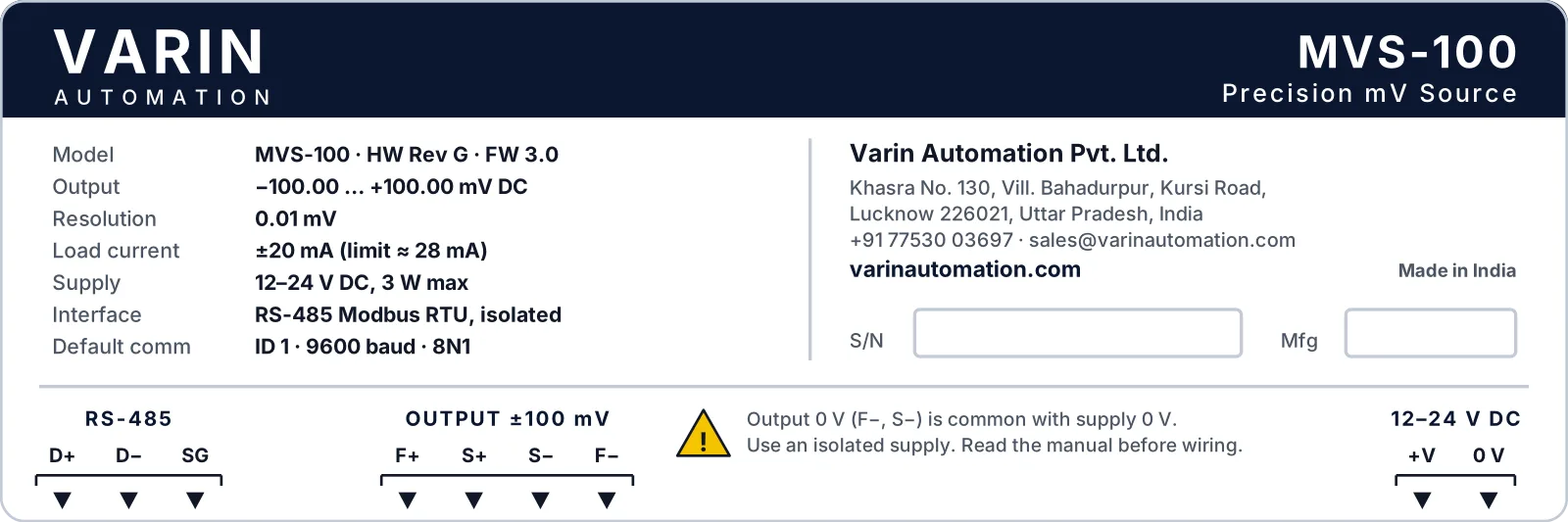
Pluggable 5.08 mm blocks, left to right as seen from the rear. For loads near 20 mA, run the SENSE wires to the load to cancel cable drop. Output 0 V is common with the supply 0 V, so use an isolated supply.
RS-485
Modbus RTU (isolated)
- D+RS-485 A
- D−RS-485 B
- SGIsolated signal ground
OUTPUT
±100 mV output
- F+FORCE+
- S+SENSE+
- S−SENSE−
- F−FORCE− / GND
POWER
12–24 V DC
- +VSupply +
- 0 VSupply 0 V
Ordering
Codes and what's included
| MVS-100 | Precision mV Source, ±100 mV, front panel + isolated RS-485 Modbus RTU |
|---|---|
| Option: HMI screens | Ready-made Delta DOPSoft / DIAScreen screens for setpoint, ON/OFF and calibration |
| Option: calibration report | Multi-point verification against a 6½-digit DMM |
| MVS-100 in DIN 144 × 72 mm housing with panel clamps |
| Mating pluggable terminal plugs for power, output and RS-485 |
| Factory calibration values, stored in the unit |
| Wiring, HMI setup and Modbus register guide |
Modbus RTU
Register map
Holding registers, 16-bit word, 1-based 4x addressing. Read 40007 = 769 (firmware v3.1) to confirm your HMI's address offset.
| Address | Register | Access | Meaning |
|---|---|---|---|
| 40001 | SETPOINT | R/W | Output in 0.01 mV, signed: −10000 … +10000 |
| 40002 | OUTPUT_EN | R/W | 0 = held at 0 mV, 1 = output on |
| 40004 | STATUS | R | Output on, clamped, calibrated, comm timeout, LOCAL mode bits |
| 40005 / 40006 | CAL_OFFSET / CAL_GAIN | R/W | Calibration offset (0.1 µV) and gain (ppm) |
| 40007 | FW_VERSION | R | 769 = v3.1 |
| 40008–40010 | SLAVE_ID / BAUD / PARITY | R/W | Communication settings (apply after save) |
| 40011–40013 | CAL_CMD / CAL_MEAS_LO / HI | R/W | 2-point calibration over Modbus |
| 40014 | COMM_TIMEOUT | R/W | Seconds, 0 = off |
| 40015 | POWERUP_MODE | R/W | 0 = start at 0 mV off, 1 = restore setpoint |
| 40016 | FP_LOCK | R/W | 1 = front panel locked by the HMI |
| 40017 | MODE | R/W | 0 = LOCAL, 1 = REMOTE |
Need it in your panel or test bench?
Add it to your basket and request a quotation, or talk to us about HMI screens and integration.
Front-panel screens
Specifications are subject to change without notice. Printed from https://varinautomation.com/products/mvs-100.